Image inpainting
There are several cases when inpainting is appropriate. It can be about removing unwanted objects from the image or targeted content modification. Then we talk about retouching. However, it can also be about repairing damaged or adding destroyed or missing parts of the image, i.e. it is a restoration of the image. The important thing is that the change happens in a visually plausible way. When filling the missing parts, from a mathematical point of view, it is an interpolation problem.
In this section, we will show two inpainting methods: inpainting based on examples (inpaintExemplar) and coherent transfer (inpaintCoherent).
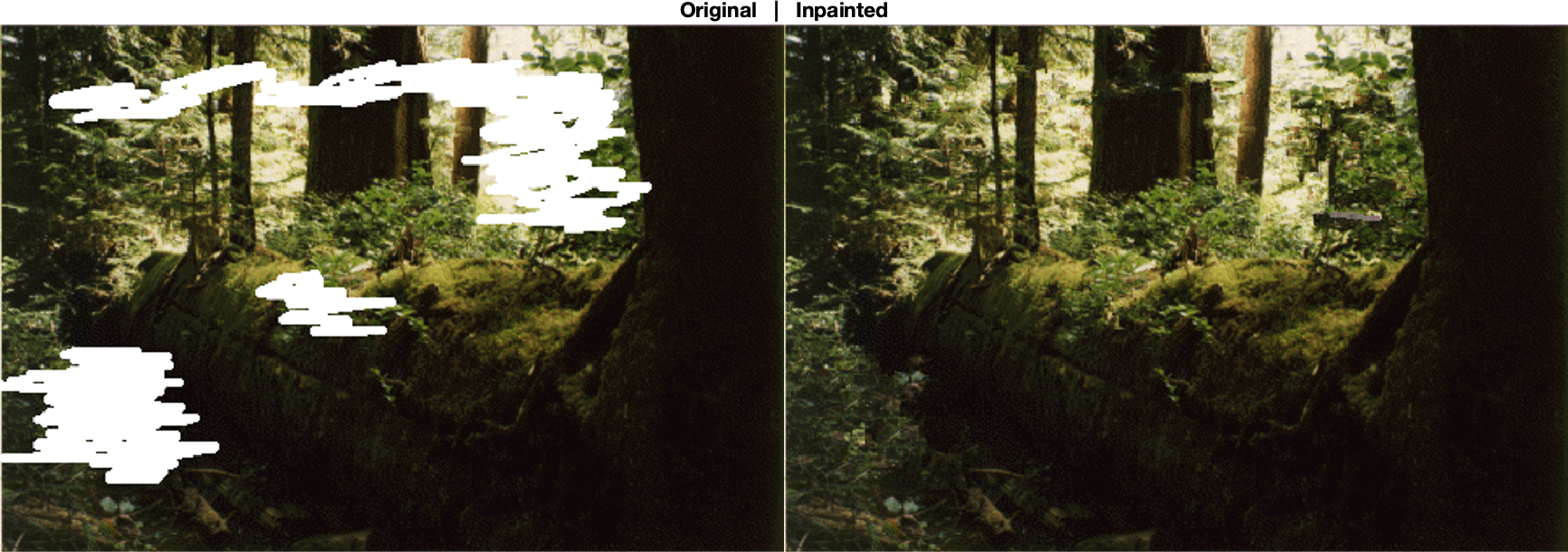
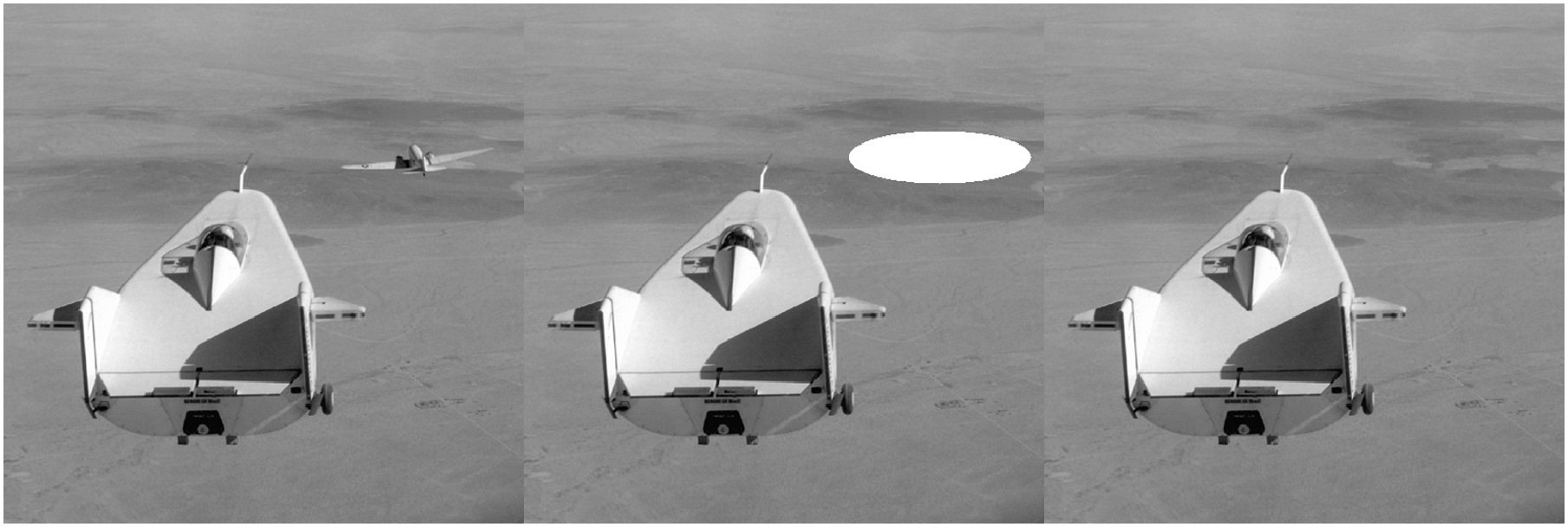
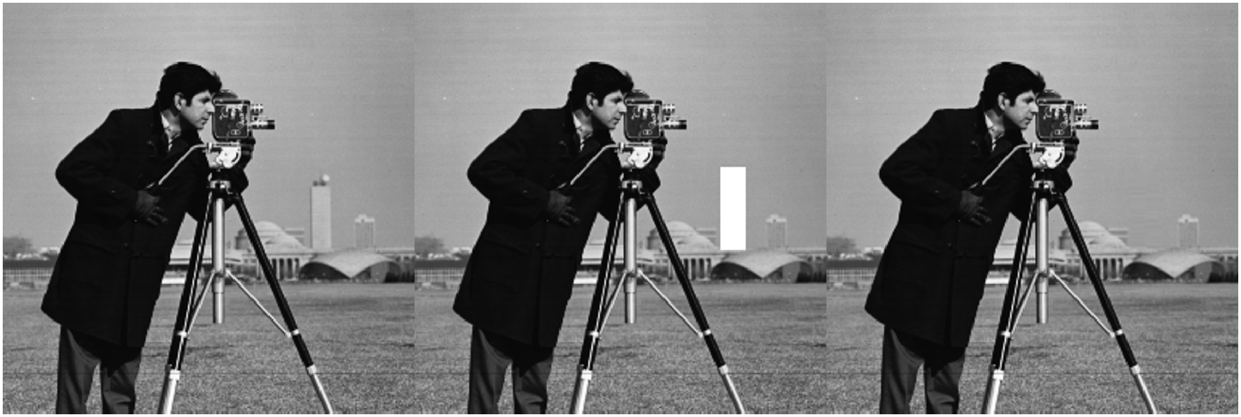
Examples of using both methods in the MATLAB environment are shown in Fig. 1 - Fig. 3, the source codes used to generate them are listed in the appendix.

Fig. 1 Example of inpainting using the exemplar based method. On the left is a damaged image (there are white areas that need to be filled), on the right is a restored image.

Fig. 2 An example of inpainting using the exemplar based method. On the left is the original image, in the middle is a white area instead of the object we want to remove, on the right is the resulting retouched image

Fig. 3 Example of inpainting using coherent transmission. On the left is the original image, in the middle is a white area instead of the object we want to remove, on the right is the resulting retouched image
In the coherent transmission method [1] is the work done at the level of image points. When inpainting in an area, it starts at the border of the area and continues towards its interior. The inpainted point value is estimated from the neighborhood of that point as a weighted average, considering either directional or diffuse information transfer from the neighborhood.
The inpainting method based on examples [2] deals with patches, which are small rectangular areas. Within the algorithm, the most suitable places to insert the patch are identified, with the center of the patch lying on the edge of the target area. A suitable patch is searched around the target area based on similarity (sum of square difference metric - SSD). The target area is step by step reduced in this way. The principle of inserting a patch is indicated in Fig. 4.

Fig. 4 The principle of inserting a patch to the edge of the target area in the inpainting method based on examples. Individual images a, b, c, d indicate the phases of the algorithm during insertion. Phase a indicates the initial situation. In phase b, the most suitable target site \(p\) for patch insertion \(\Psi_p\) is identified (green square). Subsequently, in phase c, suitable sources for the patch are found. They most likely lie somewhere on the edge that leads to the \(\Psi_p\) region.These are e.g. patches \(\Psi_{q'}\), or \(\Psi_{q''}\). Subsequently, in phase d, the most suitable patch is inserted at the target location.
References
[1] F. Bornemann and T. März. "Fast Image Inpainting Based on Coherence Transport." Journal of Mathematical Imaging and Vision. Vol. 28, 2007, pp. 259–278.
[2] Criminisi, A., P. Perez, and K. Toyama. "Region Filling and Object Removal by Exemplar-Based Image Inpainting." IEEE Transactions on Image Processing. Vol. 13, No. 9, 2004, pp. 1200–1212.
Appendix
The source code of the program that created Fig. 1
clear all; close all; clc;
I = imread('INPUT/forestdistorted.png');
mask = imread('INPUT/imagemask.png');

I(repmat(mask,[1,1,3])>0)=255;
J = inpaintExemplar(I,mask,'PatchSize',7);
montage({I,J});
title(['Original','   |   ','Inpainted'])
exportgraphics(gcf(),'inpaintExemplarExample.png')
The source code of the program that created Fig. 2
clear all; close all; clc;
I = imread('INPUT/liftingbody.png');
imshow(I,[]);
h = drawellipse('Center',[410 152],'SemiAxes',[90 26]);
mask = createMask(h);
IM=I;
IM(mask>0)=255;
J = inpaintExemplar(IM,mask);
montage({I,IM,J},"Size",[1,3]);
exportgraphics(gcf(),'inpaintExemplarExample2.png')
The source code of the program that created Fig. 3
clear all; close all; clc;
I = imread('cameraman.tif');
imshow(I,[]);
%h = drawellipse('Center',[233 160],'SemiAxes',[18 25]);
h = drawrectangle('Position',[190 102 16 52]);
mask = createMask(h);
IM=I;
IM(mask>0)=255;
J = inpaintCoherent(IM,mask,"Radius",1);
montage({I,IM,J},"Size",[1,3]);
exportgraphics(gcf(),['inpaintCoherentExample' ...
    '.png'])
The PDF version of this text is available here: inpainting_eng.pdf